Cybervert
A private signal hidden in an inverter's control loop, so faked sensor data gives itself away.
Harvard ES145 and independent research · 2025 to present
The problem
A grid-tied inverter acts on what its sensors tell it. Change those readings and the inverter acts on a grid that is not real, and the control loop cooperates.
A careful attacker does not have to send anything that looks wrong. A replayed window of genuine past measurements is, by construction, statistically ordinary. Watching for anomalies will not catch it, because there is no anomaly.
The idea
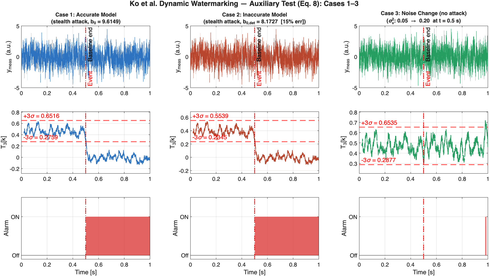
Rather than watch the measurements, change them. The inverter adds a small private random signal, a watermark, on top of its own control action. It knows what it injected, so it knows what the measured current should do in response.
If the sensor path is honest, the watermark shows up in the returned measurement with the relationship physics says it should have. If an attacker is replaying old data or synthesising their own, their data cannot contain a reaction to a random signal that was generated after the data was recorded. The correlation collapses, and the collapse is what raises the alarm. The attacker does not have to make a mistake. They just have to not be able to see the future.
The dynamic watermarking technique itself comes from the control-theory literature. My work is on making it hold up on an inverter under conditions that resemble a real feeder rather than a clean simulation.
What I built
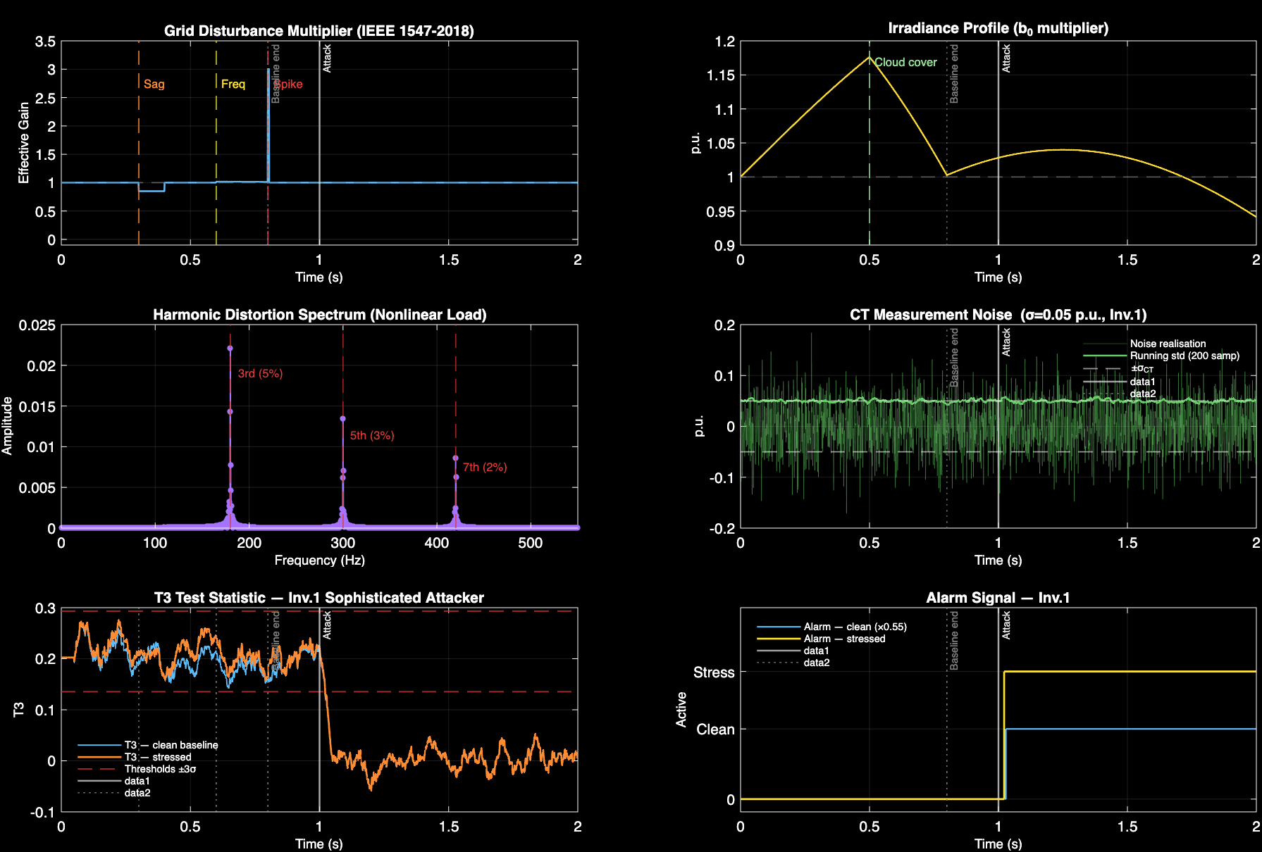
I wrote the full detection pipeline in MATLAB, from signal processing and statistical testing to automated Monte Carlo validation, reaching 98.4% attack detection with a 2.6% false-alarm rate in signal-level Monte Carlo runs. Through systematic debugging of a high-fidelity Simulink model, I traced a persistent detection failure to a broken control loop. With the loop fixed, the method worked in simulation once the underlying physics were sound.
The detector had to survive all of it without alarming, while still catching an attacker trying to stay quiet.
Where it stands
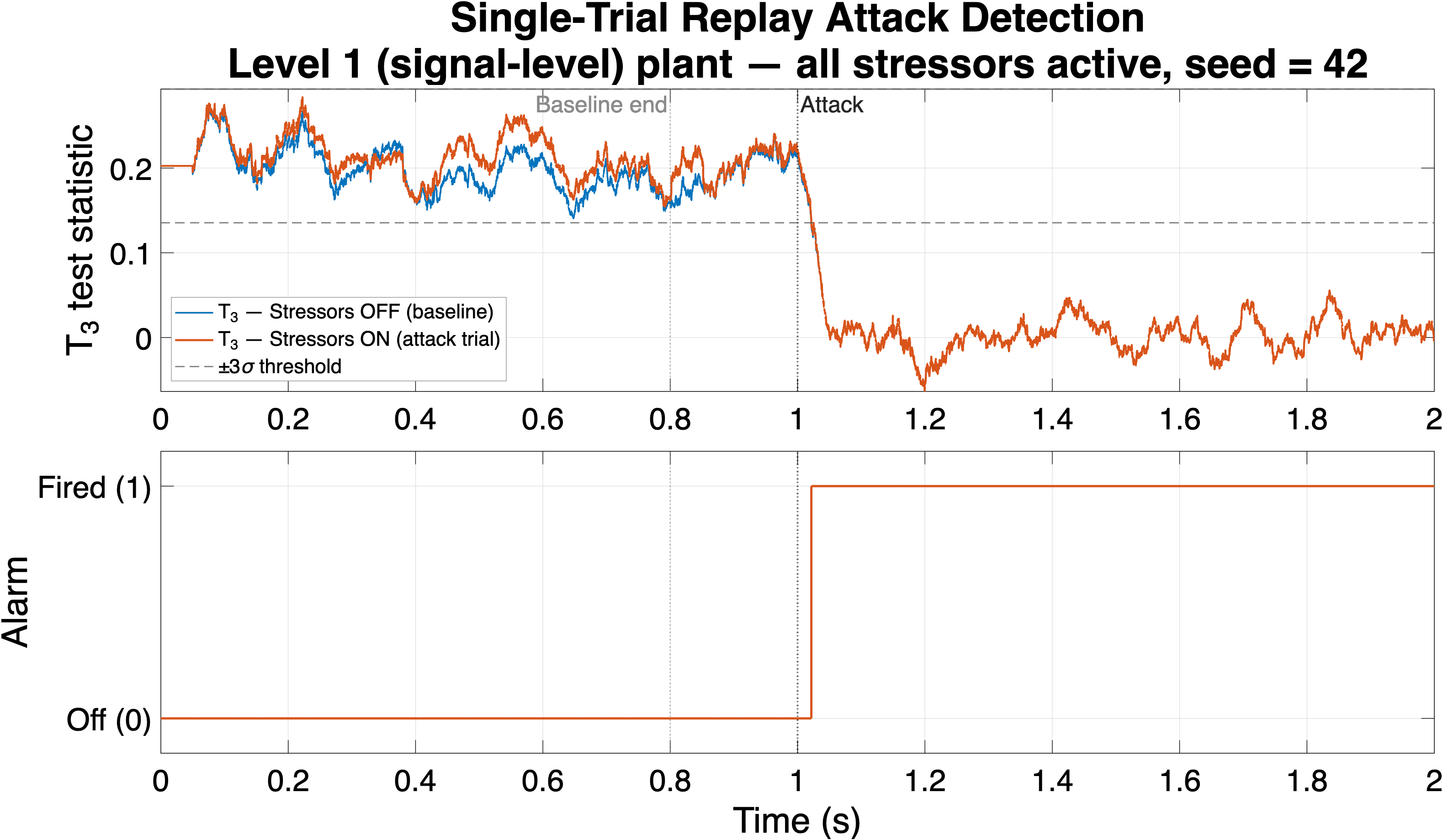
The method works on a model that genuinely tracks, under a realistic stressor profile, with the detection and false-alarm rates quoted above. It has not been validated on hardware in the loop, and I do not claim a maturity level it has not earned. The next real step is hardware, and after that the more interesting question, which is what an inverter should safely do in the seconds after the alarm fires rather than merely that it fired.
Stack
MATLAB and Simulink, with Simscape Electrical for the converter models. Monte Carlo harnesses and ablation studies in MATLAB. The project began as coursework in Harvard's ES145 and I now take it forward independently.