Microrobotics Lab electronics
Driving electronics light enough to ride on a robot the size of a housefly.
Harvard Microrobotics Lab · 2025 to present
The problem
An insect-scale robot can only carry what it can lift. A microrobot cannot carry a normal circuit board, a normal battery, or a normal microcontroller, so the electronics that drive its actuators have to shrink and lighten by roughly the same factor the robot did. The low-voltage voice-coil actuators used in the lab want a bidirectional drive signal at only 1 to 2 V. Very little off-the-shelf drive circuitry is designed to swing that low, that small, and that light.
I work on two answers, which trade against each other.
What I built
A driver with no microcontroller in it
The first approach removes the processor entirely. I designed a comparator-based relaxation oscillator whose frequency and duty cycle are both tunable, covering roughly 0.7 to 136 Hz. I derived an analytical model for it and then validated that model twice, once in simulation and once on real hardware, so the component values can be chosen from the equations rather than by sweeping parts on a bench.
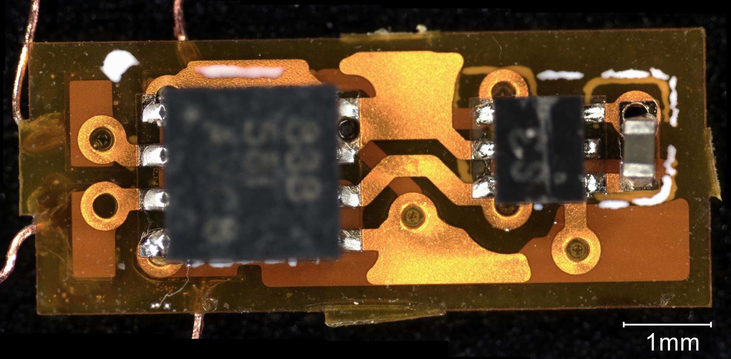
The oscillator feeds an H-bridge output stage that turns its single-ended output into a bidirectional, biphasic 2 V waveform, which is what the actuator actually wants. The whole circuit, oscillator and output stage together, fits on a board of about 7.6 × 3 mm weighing roughly 18 mg.
A driver that can be programmed
The second approach accepts a microcontroller in exchange for control. It generates a 20 kHz PWM carrier with a software-defined spike-and-hold envelope, which lets the drive waveform have a high-current phase to get the actuator moving and a lower-current phase to hold it, rather than burning the peak current for the whole cycle.
It drives six H-bridge channels at fixed 60° phase offsets. A walking robot needs its legs coordinated rather than merely driven, and that is how gaits for robots like the Harvard Ambulatory Microrobot are built. The firmware runs on an MSPM0 part in C.
Where it stands
The microcontroller-free oscillator is modelled, simulated, built, and has driven a microrobot. The six-channel programmable driver runs and produces coordinated gait waveforms.
Stack
LTspice and analytical modelling for the oscillator. KiCad and EasyEDA for board layout, on flexible polyimide as well as rigid substrates. C firmware on MSPM0 microcontrollers. Bench work with oscilloscopes and current probes, plus the PCB assembly and rework that goes with parts this small.